
Following the article from my colleague, Svein Normann, on how gas migration during and after a cement job could lead to a catastrophic disaster, we received a significant amount of questions on what we would recommend to avoid such an unfortunate chain of events from unfolding on another rig.
In this two pieces article, we'll attempt to cover the approaches towards the designing of slurries for zonal isolation in front of gas-bearing reservoirs with the potential for natural flow.
For your reference, Svein's article can be viewed here
Lets start by remembering that gas migrates thru three different and well-differentiated paths:
- Channels along the annulus.
- Loss of seal between cement and casing or formation.
- Gas invades the liquid slurry as result of insufficient hydrostatic pressure or the excessive loss of it during cement hydration (“Transition time”).
Knowing the mechanisms of gas migration we can start enumerating the keys to prevent and mitigate the invasion and migration of gas through the annulus during and after the cement job:
- Ensure proper mud removal.
- Prevent and counteract mechanical stresses.
- Design a “gas-tight” slurry with no free water content, shrinkage nor retrogression.
Mud removal
A topic worth a whole article -which we will revisit in the weeks to come- sufficient to say for now that in a cementing operation facing the risk of gas invasion, one can’t tolerate any mud left in the hole. Even a thin mud cake adhered to the pipe or the formation walls, with time, will dry off and leave an open path for formation fluids or gas to invade and migrate.
In this article, we will only mention that for a slurry to be considered appropriate to displace the hole fully, it should meet certain conditions on density and viscosity. The general rule of thumb is that a displacing fluid should have a density at least 10% above that of the fluid it's displacing; and exert a friction pressure against the wellbore walls that is at least 20% above the last. So, for the slurry to be appropriate for mud removal, a hierarchy of densities and rheologies must be respected.
Read more: A simplistic approach to testing the cement slurry before every job [from API10B2]
Mechanical stresses.
Cement is a material that, despite its significant compressive strength, shows very little flexibility and therefore can fail under elongation forces.
In his article, Svein explains how cement could suffer “…Mechanical damages (…) caused by stresses associated to pressure changes, temperature changes, geo-mechanical forces, etc”. He also gives us a few examples on how this can occur.
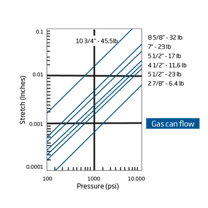
The important lesson from Svein is that engineers in charge of preparing completion and workover programs need to be mindful of the limitations of the set cement and avoid unnecessary application of pressure against the wellbore. Pressurization of the casing (even by displacement with heavier fluids) will create a “ballooning” effect in the pipe. This will apply large radial forces against the cement sheet outside of it which could lead to its failure. As you can see in the following graph, less than 1,000 psi of differential pressure is sufficient to create more than the stretch the gas needs to flow behind most production casing sizes.
Nowadays, when the use of hydraulic fracturing to unlock unconventional resources has become so widely spread, cement must in some cases withstand wellhead pressures above 10,000 psi, which means forces well beyond what most cements can handle safely. Cementing providers and operators are more often using cements that are considered “flexible” and are capable to better handling the impact of temperature changes, mechanical stresses, etc.
For today’s chapter, we'll focus only on mechanical failures that are associated with two phenomena more relevant for conventional cements: Retrogression and shrinkage.
Correctly designing a gas-tight slurry should prevent the first one and fix the second one.
Designing a gas-tight slurry
When facing a gas migration scenario for a cement job, you should consider the following aspects to design a “gas-tight” cement slurry.
- Retrogression effect on the cement
- Counteracting cement natural shrinkage
- No free water
- Low fluid loss
- Quick Gel Strength development and right angle setting time.
- Slurry porosity/permeability.
Retrogression
The cement (besides minor amounts of free lime, other oxides and gypsum) is made of four main compounds: Tricalcium silicate (C3S), Dicalcium silicate (C2S), Tricalcium aluminate (C3A) and Tetracalcium aluminoferrite (C4AF).
When mixed with water, silicates C3S and C2S (which constitute up to 80 % of cement) produce calcium-silicate-hydrate C3S2H3, also called C-S-H gel, which comprises roughly 70% of the set cement and gives cement its strength.
Above 110°C [230 °F], depending on the Calcium/Silicate ratio, the C-S-H gel converts to dicalcium silicate hydrate (α-C2SH), a compound that is highly crystalline and denser than the C-S-H. As a result, shrinkage occurs, thus damaging the integrity of the set cement and increasing its permeability. This phenomenon is termed strength retrogression. This change will cause the cement to become brittle and susceptible to severe damages from small disturbances. The retrogression will cause fractures in the cement that could be large enough for gas to flow.
The solution thought sits on the root of the problem. The production of α-C2SH from the C-S-H gel requires not only high temperatures but also a C/S ratio of 1.5 to 2.0.Formation of α-C2SH, and therefore the retrogression effect, can be prevented by adding 35-40% BWOC of silica to the cement, which alters the C/S-ratio to about 0.8-1.0.
The C-S-H gel then produces different calcium silicate phases (Tobermorite, Xonolite and Gyrolite), which all have low permeability and high strength, thus preserving the cement properties.
NOTE: Retrogression is a process that occurs in set cement a few weeks after it sets. For all considerations on this regards engineers must refer to bottom hole static temperatures (BHST).
Shrinkage
Naturally, when cement sets, it reduces its volume by 4-6% which could cause the creation of a micro-annulus that allows gas to flow.
The easier way to counteract this phenomenon is to add expansive agents to the cement to achieve 1% volumetric expansion at the specific BHST.
Expansive cements change in bulk volume after some degree of initial hardening has taken place. Controlled expansion can help to seal micro annuli, improve bonding and therefore zonal isolation. The expanding cement will be restrained by the casing and formation (when competent), so once void spaces have been eliminated, further expansion is translated into a reduction of internal cement porosity.
There are two principal techniques for inducing expansion in Portland cement:
- Gas generation (inside the cement), as result of chemical reactions between alkalis in the cement slurry and added aluminum powder, that causes expansion of the cement. The volume expansion depends on pressure and the concentration of aluminum powder. This technique is effective in shallow gas applications.
- Crystal growth, which relies on the nucleation and growth of certain mineral species within the set cement matrix due to:
- The formation of ettringite crystals which have a greater bulk volume than the components of which they form. Up to 0.25% linear expansion after 2 - 3 weeks can be achieved. Above about 177°F (77 °C), the ettringite convert to a denser calcium sulpho-aluminate hydrate and gypsum. Thus, a significant expansion will not occur at such temperatures.
- Salt cement systems where expansion occurs due to the crystallization of salts after the cement has set. The greater the salt content, the greater the expansion. Expansions of about 0.3 - 0.4% can be achieved.
- A more widely used technique is the use of magnesium oxide. It hydrates to magnesium hydroxide, which occupies more space, thus providing an expansive force within the cement. Linear expansions greater than 1.5% can be achieved. The systems require concentration of 0.25 - 1.0 %BWOC. This is effective up to temperatures of 550°F but occurs too slowly at temperatures below 140 °F to be practically beneficial.
Read more: Standards you need to know when designing a cement slurry for oil well applications
Free water
The concept of free water is already reviewed in a previous article. But briefly explained, in horizontal sections, water that segregates from the cement matrix during the hydration process will set itself on top of the cement column. In horizontal sections, this water could coalesce becoming a flow path that connects the entire interval and allows for fluids and gas migration.
Simply put, free water is a “No-Go” condition in a gas-tight slurry.
Read more: A simplistic approach to testing the cement before every job [from API10B2]
As we intend to keep the length of our blog posts down to a certain limit, we decided to keep the three key lab tests for a gas-tight slurry together for next week's piece. We’ll review the special requirements for fluid loss on a slurry facing gas migration, as well as two tests exclusively for cases where the risk of gas migration exist: Gel Strength development and Gas migration Go-No-Go tests.
See you all next week!

